The Girling Mk2 Servo
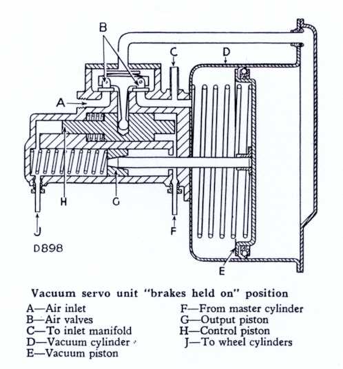 This drawing from the workshop manual shows the servo in simplified form.
The servo on the 110 gives a boost ratio of 2.78:1 and is determined by the ratio of areas of either end of a
control piston (H). The vacuum cylinder (D)contains a large piston (E) ,
the left hand side of which is constantly under vacuum supplied by the suction in the inlet manifold when the engine
is running against a closed throttle. This is of course guaranteed while braking because you brake and accelerate with
the same foot! The right hand side of the vacuum piston is either exposed to an equal vacuum,
under which condition the large "bed-spring" pushes the piston fully to the right, or atmospheric pressure,
which drives the plunger onto the hydraulic output piston (G) The vacuum on the right hand side is determined by the
air valves (B) which are opened and closed by movement of the hydraulic control piston (H).
Because the control piston is of smaller area at the left hand end,
it will move to the left unless the fluid pressure on the left hand side is greater than that on the right by a
similar ratio. The movement of the control piston exposes the right hand side of the vacuum piston to either air
or vacuum so pressurising the fluid to the wheel cylinders in the appropriate ratio to return the control piston to
its central position.
This drawing from the workshop manual shows the servo in simplified form.
The servo on the 110 gives a boost ratio of 2.78:1 and is determined by the ratio of areas of either end of a
control piston (H). The vacuum cylinder (D)contains a large piston (E) ,
the left hand side of which is constantly under vacuum supplied by the suction in the inlet manifold when the engine
is running against a closed throttle. This is of course guaranteed while braking because you brake and accelerate with
the same foot! The right hand side of the vacuum piston is either exposed to an equal vacuum,
under which condition the large "bed-spring" pushes the piston fully to the right, or atmospheric pressure,
which drives the plunger onto the hydraulic output piston (G) The vacuum on the right hand side is determined by the
air valves (B) which are opened and closed by movement of the hydraulic control piston (H).
Because the control piston is of smaller area at the left hand end,
it will move to the left unless the fluid pressure on the left hand side is greater than that on the right by a
similar ratio. The movement of the control piston exposes the right hand side of the vacuum piston to either air
or vacuum so pressurising the fluid to the wheel cylinders in the appropriate ratio to return the control piston to
its central position.
One key thing to note is that the plunger actually blocks a recuperation hole in the output piston (G)
as it pushes onto it.
This means that if for some reason the Vacuum piston does not get returned fully to the right by the bedspring affair
when the pedal is released, then the brakes will be held on to some extent.
This can occur because the hydraulic seals leak, fluid finds its way into the vacuum cylinder and eventually soaks
into the leather seal, washing away the lubricant and causing it to bind on the cylinder wall.
Because of the way the seal sits against the wall, if it starts to bind on the return it tends to jam up even more.
A gentle "mooing" noise as the piston judders back as the brakes are released is a certain early warning sign.
Ignore it at your peril!
Sometimes the piston can jam immediately after a rebuild,
because the new sponge strip that pushes the leather against the vacuum cylinder wall is too firm.
You are better off re-using the original strip if it is serviceable, or finding a kit which has a softer strip.
By the way, if you need any convincing that it's your servo causing the jamming on,
notice that the brake light switch is on the un-boosted part of the circuit.
See the BRAKES - GENERAL LAYOUT page...
so if your brake lights are off and your brakes are on, odds are that it's the servo sticking.
If Disaster Strikes
So, let's imagine you're stuck at the lights and your brakes are on solid. To add insult to injury,
there are people muttering that old cars should be banned etc etc...
My advice although strange is to try freeing the brakes by putting them on harder
(vacuum piston a bit more to the left where the force of the bed-spring is increased)
and then releasing them suddenly (vacuum piston hopefully returns without stopping,
dynamic friction being less than static)
If this doesn't work try knocking the end of the servo casting with something
(heel of your shoe, starting handle etc, to see if this jarring will get the piston moving again.
Do not be tempted to hit the vacuum cylinder this may distort it and make it irreparable.
New units are not available! Hopefully this will release the brakes.
Once freed, don't be tempted to try them again! The next thing to do is to disconnect the vacuum hose
from the servo and bung something in the end to prevent air rushing into the manifold when the engine is running.
In my tool tray there was a tommy bar with a bobbly end that fitted the bill,
and it could be wedged out of the way behind the fuel water trap bracket too.
Do not use anything that may get sucked into the engine, and damage it!!
And still there's more... Remember is that the Girling Mk2 Servos are what are called "suspended vacuum"
servos, which means that the left hand side of the vacuum piston in the illustration above is maintained
under constant vacuum even when the servo is at rest.
This is maintained for some time even after the engine is stopped by the non return valve
in the vacuum supply banjo union, and effectively means that the servo acts as its own vacuum reservoir.
It is the inrush of atmospheric air that drives the plunger.
So what? Well, this means that even after you've managed to free the brakes,
you must not re-apply them until the suspended vacuum has been dissipated, otherwise you'll be back to square one.
The most expedient method is to loosen the nut holding the vacuum supply banjo to the top of the servo,
but this can be tight and difficult to get at. Alternatively you could just wait a couple of hours!
After all this palaver you should be able to drive the car home gingerly. The brakes will work,
but you'll need to press the pedal about 3 times harder than usual.
If all your attempts at releasing the servo fail,
it is always possible to release the fluid pressure at a caliper bleed nipple (these are accessible without
removing the wheels) and drive using the handbrake only. This is tantamount to suicide,
because often the hand brake mechanism gets neglected and there really isn't a lot of stopping power,
but speaking from experience, it is just about possible on the flat.
The footbrake can be used to perform an emergency stop, but then of course the brakes will be solid again!
Once home, rebuild the servo.....
Rebuilding the Servo
Click here for a copy of the instructions that come with the seal kit.
These may take quite a while to download,
since there's about half a megabyte of data, but you should at least be able to read the first page while
the subsequent ones download. Don't attempt to dismantle the servo without reading these first,
because careless disassembly can wreck the air valve.
The January 1994 issue of Practical Classics Magazine contains a really first class article
about rebuilding the Girling Mk2 servo. There are step by step instructions with 19 colour photos showing what to do.
If you plan to rebuild your servo you could see if your local library can get you a copy.
You can click here for an exploded view of the servo,
which shows the earlier Mk2 with the two part control piston.
The hole in the output piston (24A) is not shown in this view for some reason.
Paul Norton of Norton Classic Servos (Tel: 01494 563254 or
email him) is extremely experienced and helpful and is
one of the few people who can supply the seal kits for the earlier servos, including the Clayton Dewandre
type used on the 1956-58 and early 1959 90 models.
He also offers a reconditioning service if you don't want to do the job yourself.
Bleeding the system after a servo rebuild
As you have seen, the servo contains many chambers where pockets of air can get trapped.
These are best eliminated by getting plenty of flow going when bleeding the brakes, so that the turbulence
forces fluid into all the corners.
It is generally considered that brake bleeding aids that work by applying pressure to the fluid header tank,
do not achieve sufficient flow to purge the servo satisfactorily.
In addition to this, they place the low pressure seal in the master cylinder under more strain
than it was designed to handle.
If you are not sure of the condition of your master cylinder,
it may be prudent to avoid these bleeding devices all together.
BACK TO THE TECHNICAL MENU
HOME